Pwm Driver Circuit For Stepper Motor
Geovision V8 Software. Consequences Of Not Activating Software Piracy there. With our new project,, we are very keen to support the development of open source control software for laser cutters. We are more than happy for people to modify our, replace the control system with something suitably open source and then let us know how it goes. Realistically though we're going to have to figure these things out for ourselves so we can guide other people through the process.
There are a lot of tutorials online detailing the hardware PWM features of the arduino and how it relates to servo motor control. This instructable will show you how to use the hardware PWM to control a stepper motor instead.

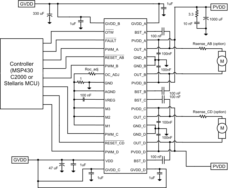
Dual stepper motor driver, pwm motor. A3966: Dual Full-Bridge PWM Motor Driver. Rs should be non-inductive, and the circuit board ground run should be as large.
Lg R200 Dual Display Driver Xp. We'll start with the basics of PWM, show briefly how it relates to servo motors and then show the differences for use with stepper motors. Pulse Width Modulation (PWM) is a technique for creating a digital square wave signal. A square wave has 3 main characteristics • Amplitude - The amount the signal changes between On and Off states • Frequency - The number of times the signal repeats in a given time frame • Duty Cycle - The proportion of On time to Off time usually expressed as a percentage In these digital systems the amplitude is fixed between 0 and 1, between 0V and VCC. In my testing this was +5V.
In it's simplest form a PWM square wave can be created with a few lines of code. The following code would produce a signal with a 1 second Frequency and a 10% duty cycle. This would be functional but the Arduino would be dedicated to producing this signal the whole time and would not do anything else.